DXF design rules for laser-cut nickel tabs
A nickel tab is not only an outline. It must account for the assembly, weld points, BMS passages, insulated areas and handling all the way to the pack.
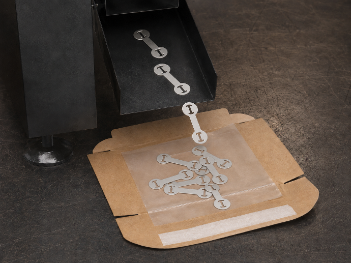
Start from the real assembly
The shape should come from the real battery pack, not only from a theoretical drawing. Cell spacing, weld point position, current output, cable routing, BMS, insulation and housing constraints all affect the geometry. The DXF must turn those constraints into simple, clean and usable contours.
A good part is often less spectacular than a complex drawing: it keeps material where conduction or welding is needed, removes material where clearance or insulation is needed, and avoids details that make the part fragile for no benefit.
Geometry points to check
Before sending a DXF file, the geometry should be checked as a technical part, not only as a visual drawing. The goal is to make sure the file can be read, analysed, cut, handled and used without unnecessary back-and-forth.
- Closed outer contour.
- Clean and closed internal cut-outs.
- Widths consistent with the intended use.
- No unnecessarily thin bridges.
- Clean radii or transitions where the shape changes direction.
- Enough access for welding electrodes.
- No dimension lines inside the cutting geometry.
- No duplicate or overlapping segments.
Simple geometry is often the safest geometry.
For thin nickel parts, the drawing has to work beyond the screen: it must be cut, removed, checked, packed and welded without adding fragile details.
Details that complicate production
Micro-details, very sharp internal angles, unnecessary slots, contours that are too close and extremely thin shapes can complicate cutting and handling. Even if laser cutting can be precise, a thin part still has to be removed, checked, packed and used without bending.
The most useful DXF files are usually simple and intentional. Each cut-out should have a reason: clearance, insulation, positioning, electrode access or assembly constraint. If a detail does not help the pack, the weld or the handling, it may only add risk.
Think about the part after cutting
A nickel part must arrive usable: flat, identifiable and compatible with the assembly. The drawing should account for how the part will be handled, placed on the pack, welded and insulated. A visually elegant but fragile geometry can waste time during assembly.
The DXF should also make future reordering easier. When the geometry is clean and the version is clear, the same part can be ordered again with less uncertainty. This is especially useful for prototypes, workshop validation and small batches.
After the geometry, check the spot welding constraints.
Design quality is not only about the cut path. The part also needs to remain usable during the welding operation.
Spot welding pure nickel tabs →DXF design rules for laser-cut nickel tabs
A nickel tab is not only an outline. It must account for the assembly, weld points, BMS passages, insulated areas and handling all the way to the pack.
Start from the real assembly
The shape should come from the real battery pack, not only from a theoretical drawing. Cell spacing, weld point position, current output, cable routing, BMS, insulation and housing constraints all affect the geometry. The DXF must turn those constraints into simple, clean and usable contours.
A good part is often less spectacular than a complex drawing: it keeps material where conduction or welding is needed, removes material where clearance or insulation is needed, and avoids details that make the part fragile for no benefit.
Geometry points to check
Before sending a DXF file, the geometry should be checked as a technical part, not only as a visual drawing. The goal is to make sure the file can be read, analysed, cut, handled and used without unnecessary back-and-forth.
- Closed outer contour.
- Clean and closed internal cut-outs.
- Widths consistent with the intended use.
- No unnecessarily thin bridges.
- Clean radii or transitions where the shape changes direction.
- Enough access for welding electrodes.
- No dimension lines inside the cutting geometry.
- No duplicate or overlapping segments.
Simple geometry is often the safest geometry.
For thin nickel parts, the drawing has to work beyond the screen: it must be cut, removed, checked, packed and welded without adding fragile details.
Details that complicate production
Micro-details, very sharp internal angles, unnecessary slots, contours that are too close and extremely thin shapes can complicate cutting and handling. Even if laser cutting can be precise, a thin part still has to be removed, checked, packed and used without bending.
The most useful DXF files are usually simple and intentional. Each cut-out should have a reason: clearance, insulation, positioning, electrode access or assembly constraint. If a detail does not help the pack, the weld or the handling, it may only add risk.
Think about the part after cutting
A nickel part must arrive usable: flat, identifiable and compatible with the assembly. The drawing should account for how the part will be handled, placed on the pack, welded and insulated. A visually elegant but fragile geometry can waste time during assembly.
The DXF should also make future reordering easier. When the geometry is clean and the version is clear, the same part can be ordered again with less uncertainty. This is especially useful for prototypes, workshop validation and small batches.
After the geometry, check the spot welding constraints.
Design quality is not only about the cut path. The part also needs to remain usable during the welding operation.
Spot welding pure nickel tabs →